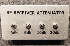
RF ATTENUATOR (Receive Only)
USES FOR AN RF ATTENUATOR
An RF (Radio Frequency) attenuator is a device used in RF circuits to reduce the power level of a signal without significantly distorting its waveform. Attenuators are commonly used in various applications to manage signal levels, protect sensitive equipment, improve radio direction finding accuracy, and to assist finding sources of RF radio interference.
- Signal Level Adjustment: In RF systems, it is often necessary to adjust the signal level to match the input requirements of different components, such as an amplifiers or receivers. An RF attenuator can reduce the signal power to a suitable level.
- Protecting Sensitive Equipment: High-power RF signals can damage sensitive components in test equipment, such as VNAs and spectrum analyzers. Attenuators are used to reduce the power to a safe level before it reaches these devices.
- Radio Direction Finding: When a hand held receiver and directional antenna is used to locate a source of RF signals, a signal attenuator is needed to limit the receive signal level. As you get closer to the signal source, the signal becomes stronger. Without an attenuator, the signal can become so strong that it overloads the receiver, causing distortion, inaccurate signal strength readings, and making it difficult to determine the direction to the signal. While trying to determine the direction to a signal source, the attenuator should be used to reduce the received signal strength to approximately one half of your S meter scale. This makes it easier to see a rise or fall in signal level, as the antenna is rotated.
- Minimizing Interference: In environments with a lot of RF noise or interference, using an attenuator can help by lowering the desired signal level to just above the noise floor. This makes the detection of the signal easier by eliminating signals below the level of the desired signal.
- Assist finding sources of radio interference: This is similar to radio direction finding, but incorporates the use of computer software to plot the signal levels of the interference signal as the receiver is moved. The use of an RF attenuator, similar to the one in this document, is described in the W4DD Presentation of RFI Interference. The presentation was made on September 8th 2022, using the ECR Zoom Room. The presentation can be viewed at https://www.youtube.com/watch?v=tBujP5Tm3Ug.
CIRCUIT DESCRIPTION
This design utilizes a string of PI attenuator stages. Each stage is independent of the others in the attenuator string. By using the correct resistance values for the parallel and series resistors, the input and output impedance of each stage is equal to approximately 50 ohms. This allows adding additional stages without effecting the operation of the others stages in the string. For example, if you need to add an additional 20 DB of attenuation, just duplicate stage 4 of the schematic (S4, R10, R11, and R12) between the original stage 4 and connector J2.
RF ATTENUATOR OPERATION
When an input signal is connected to J1, switch S1 can be set to bypass the first PI attenuator stage, which connects the signal directly to the second stage. If the switch connects the signal through the first stage, the resistor values for that stage determines the insertion loss. This attenuated signal is then connected to the second stage. This process is repeated for all stages. To calculate the total attenuation, add the attenuation of each stage that is connected. The sum is the total attenuation.
CONSTRUCTION DETAILS
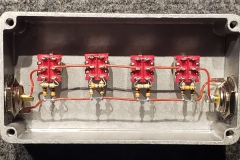
This is a very simple build that can be customized to fit your needs. Almost any sealed metal box can be used. The input and output connectors can be UHF type bulkhead connectors, but BNC bulkhead connectors will also work. Almost any type of insulated wire is satisfactory.
The bill of material specifies low inductance resistors for the assembly. Finding through hole low inductance resistors is becoming more difficult as time goes by. The preferred resistors would have been carbon composition resistors like the obsolete RCR series of resistors. The next best would be low inductance metal film resistors designed for high frequency use. Since these are difficult to find, and often several dollars per resistor, I called out generic 5% metal film resistors on the bill of materials. (Each of the resistance values called out are standard 5% values.)
BILL OF MATERIALS
—————————————————————————
(4) DPDT SWITCH, MINI, 7201SYZQE, C&K
(2) UHF BULKHEAD CONNECTOR, PE44060, PASTERNACK
(1) BOX, ZINC, 112x62x31, 1590K430 , HAMMOND
(2) RESISTOR, 300 OHM, 1/4W, 5%, LOW INDUCTANCE
(2) RESISTOR, 240 OHM, 1/4W, 5%, LOW INDUCTANCE
(2) RESISTOR, 150 OHM, 1/4W, 5%, LOW INDUCTANCE
(2) RESISTOR, 100 OHM, 1/4W, 5%, LOW INDUCTANCE
(2) RESISTOR, 68 OHM, 1/4W, 5%, LOW INDUCTANCE
(2) RESISTOR, 62 OHM, 1/4W, 5%, LOW INDUCTANCE
(2) RESISTOR, 39 OHM, 1/4W, 5%, LOW INDUCTANCE
(2) RESISTOR, 18 OHM, 1/4W, 5%, LOW INDUCTANCE
(AR) WIRE, 24 AWG, UL1569
CONSTRUCTION OPTIONS
Because this design is intended to be used as an uncalibrated device, the 5% metal film resistors are sufficient for use. If a slightly more accurate unit is desired, consider using low inductance 1% resistors. If 1% resistors are used, they must be low inductance. If they are not, the accuracy attained will not be much better than what is obtained using 5% resistors.
The 1% resistor values are shown in the table below:
R# 1% 5%
—- ——- —–
R2 17.6 18
R3 292.4 300
R4 150.5 150
R5 37.4 39
R6 150.5 150
R7 96.2 100
R8 71.2 68
R9 96.2 100
R10 61.1 62
R11 247.5 240
R12 61.1 62

