INTELLITRON HAM STICK ANTENNA
(10 METER MA-2010T DUAL ANTENNA IN A DIPOLE CONFIGURATION)
With the corporate changes that are affecting MFJ, obtaining their Hamstick antennas has become more difficult. Several secondary sources have surfaces. One new version is Intellitron. Their Hamstick antenna seem to be in good supply, and at a fairly low price. It made good sense to do an objective test on their 10 meter MA-2010T antenna. Possibly other bands will be tested in the future.
TEST PROCEDURES
Since many of the Hamstick antennas are being used for POTA, I tested the MA-2010T antennas in a manner typically used by POTA Activators. These tests were run from a free standing support, with antenna elevations of 10’, 15’ and 20’. Since POTA activators normally don’t have access to an effective earth ground, neither the radio of metal mast were connected to earth ground.
Two different dipole adapter brackets were used. The MFJ-347 and my own custom fabricated mounts were tested. Both versions have two isolated antennas, and only the mount frames are electrically tied to the support mast. Both mounts resulted in very similar results, so only data collected from my custom mount is shown.
Before taking the tabulated data, I experimented with several configurations of feed lines. Different length of RG-8U cable with and without coiled coax chokes were tested. The antenna elevation, coax susceptibility to positioning, antenna impedance, and antenna bandwidth were all considered. The ideal feedline seems to be 50’ to 60’ of coax. A three to six turn coax choke coil, wound with twelve inch diameter turns, seemed best. The coil was located on the ground, at the base of the support mast. All charted tests were done using this coax configuration. Feed lines less than 30’ resulted in very poor results.
Since POTA Activators normally don’t retune their antennas for differences in their setup elevation, I chose a middle elevation of 15′ as the baseline. All antenna/feedline tuning was done at that setup elevation. The antenna was then tested at 10′, 15′ and 20′ of elevation. It provides a good analysis of how well a preconfigured antenna/feedline will work without the need to retune the antenna at each POTA site.
GRAPHS SHOWN FOR EACH ANTENNA CONFIGURATION
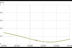
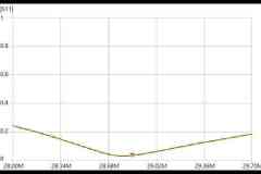
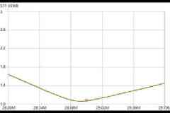
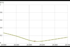
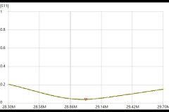
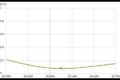
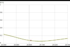
The graph labeled S11 represents the reflection coefficient or return loss charted over frequency. It is a measure of how much power is reflected back to the transmitter, from the antenna. Normally this value is given as a negative dB number, but I set this chart up to show the amount of power reflected back to the transmitter as a percentage. The 0 value indicates that 0% of the power is being reflected back, and a 1 indicates that 100% of the power is being reflected back from the antenna. Stated in another way, the 0 value indicates that there is no reflected power, so all of the power is being transmitted out of the antenna. (Note: The value of S11 is a complex calculation with numerous parameters. The over simplified version of S11 is commonly called reflection coefficient or return loss. Under most conditions, the resultant is more accurate than needed for amateur radio use.)
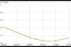
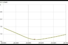
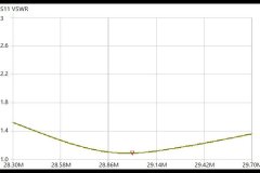
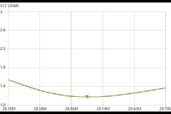
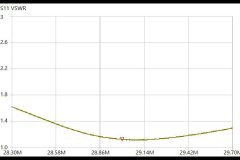
The VSWR graph represents the voltage standing wave ratio, or more commonly called the SWR by Hams. It is always a ratio of some variable number compared to 1, or 1.5:1. An over simplified explanation, is that it is the ratio of the antenna voltage for the antenna being measured, compared to the voltage of a perfectly match antenna.
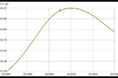
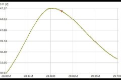
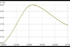
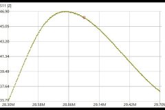
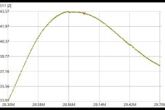
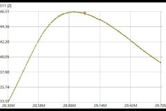
The graph labeled as S11|Z| is a measure of the AC impedance of the antenna charted over frequency. It is the vector sum of the capacitive reactance, inductive reactance, and resistance. These values combine to show the true impedance of an antenna. Very seldom does an antenna actually have an impedance that it is listed for, and never does the impedance remain constant over frequency.
Graphs were run for two different sections of the 10 meter band. The full band width including data, and phone (28.00 to 29.70) are listed as Band. The antenna was tuned to 28.85 MHZ. The phone only section (28.30 to 29.70) is called Phone, and the antenna was tuned for 29.00 MHZ.
The graphic file names all share a standard format. It is HIS_10m_Phone_20’_S11.jpg. The IHS stands for Intellitron Ham Stick, 10m stands for 10 Meters, 20’ stands for antenna elevation, and S11 stands for what is on the graph.
RESULTS
(1) It was surprising to see that all of the antenna configurations would provide satisfactory VSWR levels over the phone portion of the band, without a built in or external tuner. Using one would be an advantage, due to a reduction of RF voltage stress on the radio.
(2) The elevation of the antenna resulted in similar VSWR values for the 15′ and 20′ elevations. At 10′ the resonant point of the antenna rose by approximately 0.3MHZ during the 10′ phone section test, but not during the 10′ full band test. This is a really minor discrepancy, and is probably the result of feed line or coax choke positioning. This result was confirmed during the second test at 10′ elevation, without changing any of the setup.
(3) No real world RX or TX testing was done to determine the effects of elevation on the antenna radiation pattern. It would be difficult to model this dipole on antenna modeling software. The parameters of the antenna shaft choke coil are proprietary to Intellitron, so trying to model the antenna would just be a guess.
(4) From the results seen on these charts, the MA-2010T should make an excellent POTA antenna that requires very little adjusting when being set up in the field.
ANTENNA GRAPHIC FILES
This section contains the graphic files for the 10 meter antennas at an elevation of 10′, 15′ and 20′. Each thumbnail image may be clicked on for an expanded image.
Intellitron MA-2010T in a dipole configuration. Tuned for the full 10M band, centered at 28.85Mhz, and at a 10′ elevation.
Intellitron MA-2010T in a dipole configuration. Tuned for the full 10M band, centered at 28.85Mhz, and at a 15′ elevation.
Intellitron MA-2010T in a dipole configuration. Tuned for the full 10M band, centered at 28.85Mhz, and at a 20′ elevation.
Intellitron MA-2010T in a dipole configuration. Tuned for the phone section of the 10M band, centered at 29.00Mhz, and at a 10′ elevation.
Intellitron MA-2010T in a dipole configuration. Tuned for the phone section of the 10M band, centered at 29.00Mhz, and at a 15′ elevation.
Intellitron MA-2010T in a dipole configuration. Tuned for the phone section of the 10M band, centered at 29.00Mhz, and at a 20′ elevation.
